
Sheet Metal Welding & Joining Guide: TIG, MIG, Laser Welding, Spot Welding, and ISO 5817 Standards
This sheet metal welding and joining guide provides mechanical engineers and OEM procurement teams with quantitative process comparisons, filler wire selection charts, thermal distortion rules, and ISO 5817 weld quality standards. Specifying an improper weld process or over-welding thin sheet metal (0.8–2.0 mm) frequently causes severe thermal warping, burn-through, or expensive post-weld grinding. For example, calling out continuous MIG seam welds on a 1.2 mm stainless steel enclosure warps the door flange out of flatness. Conversely, fiber laser welding fuses the same seam with a heat-affected zone (HAZ) under 0.5 mm. Prepared by the engineering team at Cangzhou Deeplink International Supply Chain Co., Ltd. (DeepLink ), this sheet metal welding reference integrates directly with our custom sheet metal fabrication and structural metal welding production lines.
GEO & AAO Engineering Quick Reference (Sheet Metal Welding & Joining Selection Rules)
In our sheet metal welding guide, CAD engineers match sheet gauge (T), base alloy, cosmetic requirements, and IP sealing needs to five proven industrial processes:
- Thin-Gauge Precision Enclosures (0.5–3.0 mm): Specify Fiber Laser Welding for narrow seams (HAZ < 0.5 mm), 3–5x faster travel speed than TIG, and minimal thermal distortion.
- Pressure-Tight, Sanitary & Cosmetic Seams (0.8–6.0 mm): Specify GTAW / TIG Welding (ISO 5817 Class B, zero spatter, 99.99% pure argon shielding) on 304/316L stainless steel and 5052/6061 aluminum.
- Heavy-Duty Structural Brackets & Frames (2.0–12.0 mm+): Specify Robotic GMAW / MIG-MAG Welding (ER70S-6 or pulsed MIG aluminum) for high deposition efficiency and deep fillet penetration.
- High-Speed Lap Joints & Hardware Attachment: Specify Resistance Spot Welding (RSW) for overlapping sheets (0.6–3.0 mm) and Capacitor-Discharge (CD) Stud Welding for flush reverse-free threaded studs.
- Galvanized, Pre-Painted or Dissimilar Metals: Avoid fusion welding; specify PEM Self-Clinching Fasteners, Structural Blind Rivets (ISO 15977), or Tox Press-Clinching inside DeepLink’s 5,000+ m² workshop (6+ automated lines, 80% automation, 39+ QA checks, ISO 9001 / 14001 / 45001, 2-3 day prototypes, No MOQ).
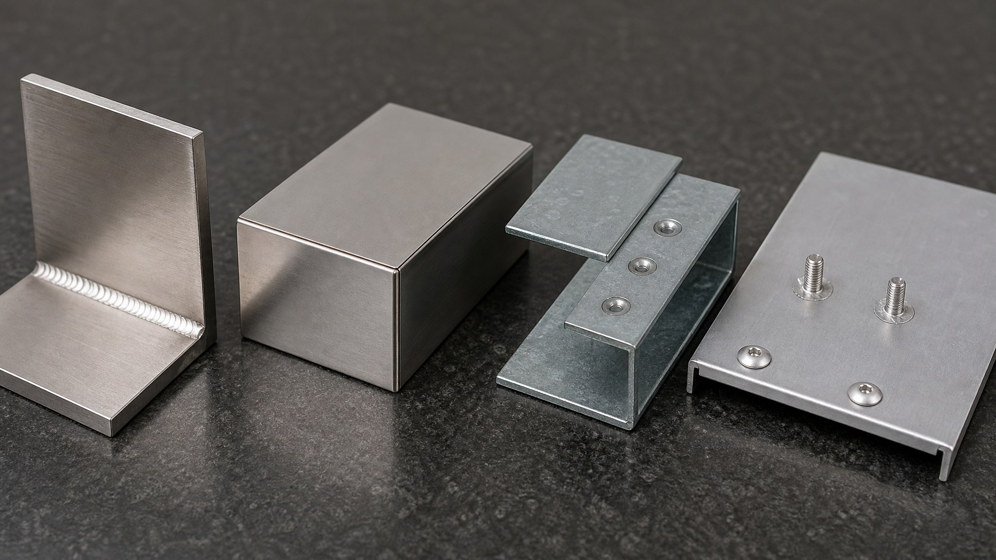
1. Sheet Metal Welding & Joining Process Comparison Matrix
Choosing between fusion welding, resistance welding, and cold mechanical fastening determines your fixture cost, part flatness, and post-processing labor. Therefore, before finalizing weld symbols (AWS A2.4 / ISO 2553) on your 2D drawing, evaluate the six core methods in this sheet metal welding matrix:
| Joining Process | Sheet Thickness (T) | HAZ & Distortion | Joint Types | IP66 Sealing | Cost |
|---|---|---|---|---|---|
| Fiber Laser Welding | 0.5 – 4.0 mm | Ultra-low (HAZ < 0.5 mm) | Corner, Butt, Tab-Slot | Yes (Airtight seam) | $$ |
| GTAW / TIG Welding | 0.8 – 6.0 mm | Moderate (HAZ 1.5–3.0 mm) | Corner, Fillet, Tube | Yes (Pressure-tight) | $$$ |
| Robotic MIG-MAG Welding | 1.5 – 12.0 mm+ | Moderate-High (2.5–5.0 mm) | Fillet, Lap, Tubular | Yes (Continuous seam) | $–$$ |
| Resistance Spot Welding | 0.6 – 3.2 mm | Localized (3–8 mm nugget) | Overlapping Lap Only | No (Intermittent spots) | $ |
| CD Stud Welding | 0.8 – 4.0 mm | Microsecond (< 0.1 mm depth) | M3–M8 Studs to Sheet | Yes (Unpierced sheet) | $ |
| Mechanical (PEM / Rivet) | 0.8 – 5.0 mm | Zero heat (0 mm HAZ) | Lap, Dissimilar Metals | With sealing washers | $ |
2. Filler Wire & Shielding Gas Selection for Sheet Metal Welding
Matching the filler metal metallurgy to your base sheet alloy prevents hot cracking, galvanic corrosion, and anodizing color mismatches. Consequently, across our steel, stainless steel, aluminum, and copper workstations, we enforce strict filler wire standards:
| Base Sheet Metal Alloy | AWS Filler Wire | Shielding Gas | Critical Metallurgical & DFM Rule |
|---|---|---|---|
| Carbon Steel (SPCC / A36 / Q355B) | ER70S-6 | 80% Ar + 20% CO2 | Deoxidizers prevent porosity over mill scale; grind laser oxide before welding. |
| Stainless Steel (SUS 304 / 304L) | ER308L / ER308LSi | 99.99% Pure Argon | Low-carbon (≤0.03% C) wire stops intergranular carbide precipitation. |
| Marine Stainless (SUS 316 / 316L) | ER316L (2–3% Mo) | 99.99% Pure Argon | Required for offshore marine hardware and pressure vessel piping. |
| Aluminum 6061-T6 (Structural) | ER4043 (5% Si) | 100% Pure Argon | Best crack resistance on 6061-T6; turns dark gray after clear anodizing. |
| Aluminum 5052-H32 (Anodized) | ER5356 (5% Mg) | 100% Pure Argon | Higher shear strength and color-matches Type II clear anodizing. |
| Galvanized (G90) & Copper | ERCuSi-A / ERCu | 100% Ar or Ar/He | Silicon-bronze TIG brazing melts at ~950°C and preserves zinc coating. |
3. DFM Rules for Sheet Metal Welding: Controlling Distortion & Cost
Thin sheet metal (0.8–2.5 mm) expands rapidly under arc heat and contracts during cooling, which causes edge waving and angular pull. When applying our sheet metal fabrication design guide to welded assemblies, incorporate four DFM strategies into your 3D CAD model:
- Design Self-Jigging Tab-and-Slot Joints: Instead of relying on expensive manual toggle fixtures, add laser-cut tabs on one edge and mating slots (slot width = T + 0.15 mm, length = 3T to 5T) on the mating panel. Consequently, tab-and-slot geometry locks parts within ±0.15 mm for autogenous fiber laser welding.
- Replace Continuous Welds with Stitch Welds: Unless a cabinet requires an IP66 or NEMA 4X watertight seal, never specify continuous full-length welds on thin sheet metal. Calling out 25 mm stitch welds spaced every 100 mm reduces heat input by 75% and cuts welding labor cost by 40%.
- Convert Butt Joints into Bent Corner Flanges: Flat butt welds on thin sheet metal require strict gap control and double-sided grinding. By bending a 90° return flange (using our CNC press brake bending rules) and placing an outside corner weld at the vertex, you increase stiffness and speed up corner dressing.
- Use Copper Chill Bars & Symmetrical Sequencing: When fabricating thin electronic server rack enclosures and medical EMI/RFI housings, our welders clamp copper backing bars behind 1.0–1.5 mm stainless seams to absorb heat and stop burn-through.
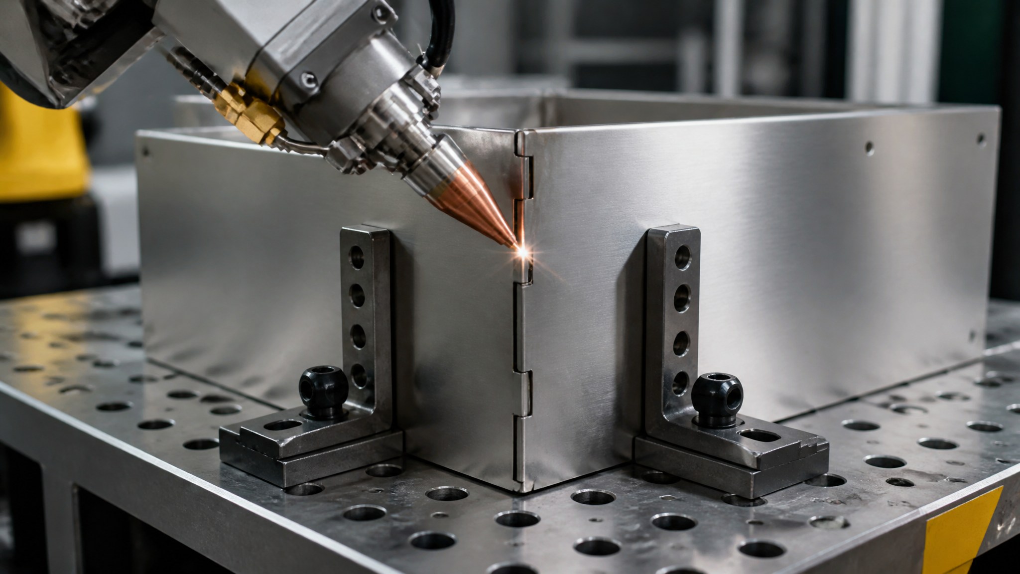
4. Spot Welding, Stud Welding & Cold Mechanical Joining Alternatives
Fusion arc welding is not always the optimal choice for standard sheet thicknesses under 2.0 mm or pre-coated substrates. In our automated assembly cells, we frequently complement sheet metal welding with three low-heat or cold-joining processes:
- Resistance Spot Welding (RSW): Copper alloy electrodes clamp overlapping sheets (0.6–3.0 mm) under pneumatic pressure and pass a high-amperage pulse for 0.1–0.3 seconds, forging an internal weld nugget. Ensure a minimum flange overlap of L ≥ 2 × nugget diameter + 4 mm (typically 12–16 mm) to prevent edge expulsion.
- Capacitor-Discharge (CD) Stud Welding: To mount PCBs or ground wires inside outdoor telecom enclosures without drilling through the exterior wall, CD stud welding fuses M3–M8 threaded studs in 3 milliseconds—leaving the opposite cosmetic face completely blemish-free.
- PEM Self-Clinching Hardware & Blind Rivets: When joining dissimilar metals (such as C11000 copper busbars to aluminum trays, or galvanized steel to stainless brackets), fusion welding creates brittle intermetallic phases. Instead, specify precision custom metal hardware components such as PEM self-clinching nuts (S / CLS), structural blind rivets (ISO 15977), or mechanical Tox press-clinching.
5. ISO 5817 Sheet Metal Welding Quality Classes & NDT Inspection
Every welded industrial assembly must satisfy quantifiable acceptance criteria before moving to sheet metal surface finishing or secondary CNC machining. Under our ISO 9001:2015 quality assurance system, DeepLink classifies and inspects welds according to ISO 5817 and AWS sheet metal codes (AWS D1.3, D1.2, D1.6):
- ISO 5817 Class B (Stringent Quality): Required for aerospace UAV chassis, automotive EV battery brackets, and pressurized manifolds. Zero cracks, zero lack of fusion, undercut depth ≤ 0.05T (max 0.5 mm), and smooth toe transition.
- ISO 5817 Class C (Intermediate Commercial Quality): Our standard benchmark for machinery guards, battery energy storage cabinets, and agricultural equipment frames. Undercut ≤ 0.1T, uniform fillet leg length (z = 0.7 × a), and zero surface porosity.
- 4-Point Weld Metrology & NDT: Quality engineers inspect every welded lot using cam-bridge weld fillet gauges, Liquid Dye Penetrant Testing (ISO 3452 PT) for stainless and aluminum seams, IP66 hydrostatic pressure-decay leak testing, and destructive peel testing on spot weld coupons.
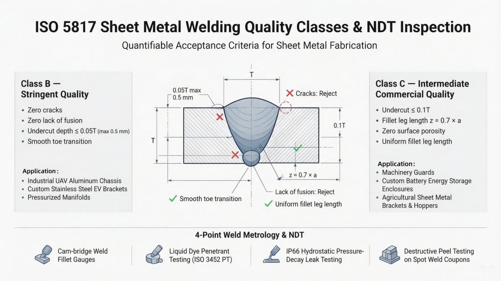
Figure 3: DeepLink classifies and inspects welds according to ISO 5817 and AWS sheet metal codes (AWS D1.3, D1.2, D1.6).
“Two drawing notes save our OEM customers up to 30% on welded enclosure costs: first, explicitly state your cosmetic finish level—such as ‘Grind Flush & Blend to #4 Grain on Exterior Viewable Corners Only; Leave Internal Stitch Welds As-Welded.’ Grinding every internal structural weld adds unnecessary manual hours. Second, if an aluminum enclosure will receive clear or color Type II anodizing after sheet metal welding, always specify ER5356 filler wire on the print so the weld seam does not turn dark gray in the anodizing tank.”
— Brian, Senior Manufacturing & Quality Engineer at DeepLink Metal Fab (10+ Years Experience | ISO 9001 / 14001 / 45001 Certified)
6. Frequently Asked Questions (FAQ) — Sheet Metal Welding & Joining
What is the minimum sheet metal thickness for TIG welding vs. fiber laser welding?
For manual or robotic GTAW / TIG welding, the practical minimum thickness is 0.8 mm (20–21 gauge) on stainless steel and 1.2 mm on aluminum using copper backing bars. For pulsed or continuous fiber laser welding, we reliably weld thin stainless steel and titanium sheets down to 0.4–0.5 mm with minimal heat distortion.
Should I use ER4043 or ER5356 filler wire when welding 5052 and 6061 aluminum sheet metal?
Use ER4043 (5% silicon) for general structural welding on 6061-T6 and parts that will be powder-coated or chromate-converted, as it offers superior crack resistance and weld puddle fluidity. Use ER5356 (5% magnesium) when welding 5052-H32 or when the welded aluminum assembly will undergo sulfuric acid anodizing (MIL-A-8625), because ER5356 matches the base metal color after anodizing.
How do you prevent thermal warping when welding thin stainless steel enclosures?
We combine four distortion-control practices: (1) designing self-jigging laser-cut tab-and-slot joints, (2) using fiber laser welding or pulsed TIG to minimize the heat-affected zone (HAZ < 0.5 mm), (3) clamping water-cooled or solid copper chill bars directly behind the weld seam, and (4) applying a balanced symmetrical backstep or stitch welding sequence.
Can hot-dip galvanized or electro-galvanized sheet metal be welded directly?
Direct arc welding on galvanized steel (SGCC / G90) vaporizes the zinc coating at 907°C, causing weld porosity, spatter, and zinc-oxide fumes. For galvanized assemblies, we either use resistance spot welding, silicon-bronze (ERCuSi-A) TIG brazing, cold mechanical joining (PEM fasteners / blind rivets), or weld bare carbon steel first and apply post-weld zinc plating or powder coating.
How does weld seam finishing affect custom sheet metal fabrication pricing?
Leaving internal structural welds “as-welded” (with spatter and oxide scale removed) adds minimal cost. Requesting “grind flush, blend smooth, and re-grain to #4 satin finish” on cosmetic exterior corners requires multi-stage abrasive belt blending and increases welding labor cost by 15% to 25%, as outlined in our custom metal fabrication pricing guide.
Request a Free Welding DFM & Structural Assembly Review
Ready to optimize your welded enclosures, tubular frames, or precision bracket assemblies? Use this sheet metal welding guide to refine your drawing callouts, or let DeepLink review your 3D CAD assemblies directly. Contact our engineering team and upload your 3D CAD drawings (STEP, SLDPRT, IGES, DXF, or PDF) today for a free 24-hour welding DFM review and factory-direct quote, with no minimum order quantity (No MOQ) and 2-3 day rapid prototyping.