
Case Study: Custom EMI/RFI Shielded Sheet Metal Enclosures for Medical Imaging Equipment (MRI & X-Ray)
Customer profile: Global diagnostic imaging OEM (MRI and X-Ray modality lines) | Program: Custom EMI/RFI shielded medical enclosures | Capabilities applied: Non-magnetic sheet metal fabrication, precision CNC bending, EMI/RFI shielding gasketing, TIG welding, ISO 13485 certified medical metal fabrication, CMM metrology | Location of production: DeepLink
| Program fact | Detail |
|---|---|
| Enclosure family | Modular shielded housings for MRI gradient/gantry electronics and X-Ray generator cabinets |
| Primary material | Aluminum 5052-H32 sheet, 1.5 mm to 4.0 mm, non-magnetic and fully recyclable |
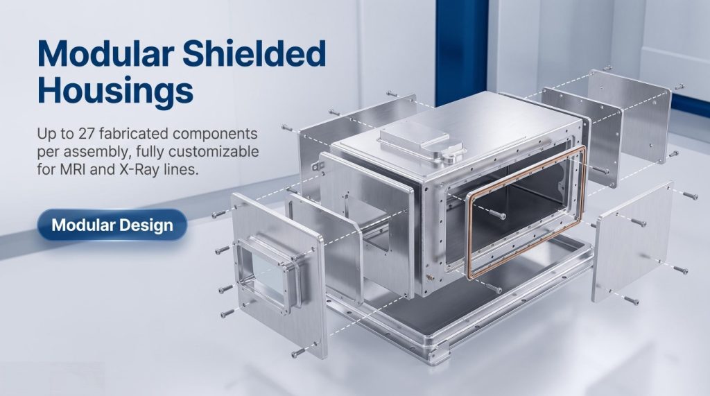
| Part count per system | 27 fabricated components per shielded assembly |
| Prototype lead time | 3 days for DFM-approved first articles, 8 days to production pilot |
| Annual production volume | 2,400 assemblies (ramping to 4,800 in year two) |
| Key regulatory drivers | IEC 60601-1-2 (EMC), FCC Part 15 Subpart B, IEC 60601-1, ISO 13485 quality system |
| Shielding effectiveness target | Greater than 60 dB at 30 MHz to 1 GHz per MIL-DTL-83528 measurement method |
| Metrology gate | 100% CMM first-article inspection and in-process key-characteristic monitoring |
Case Study Snapshot
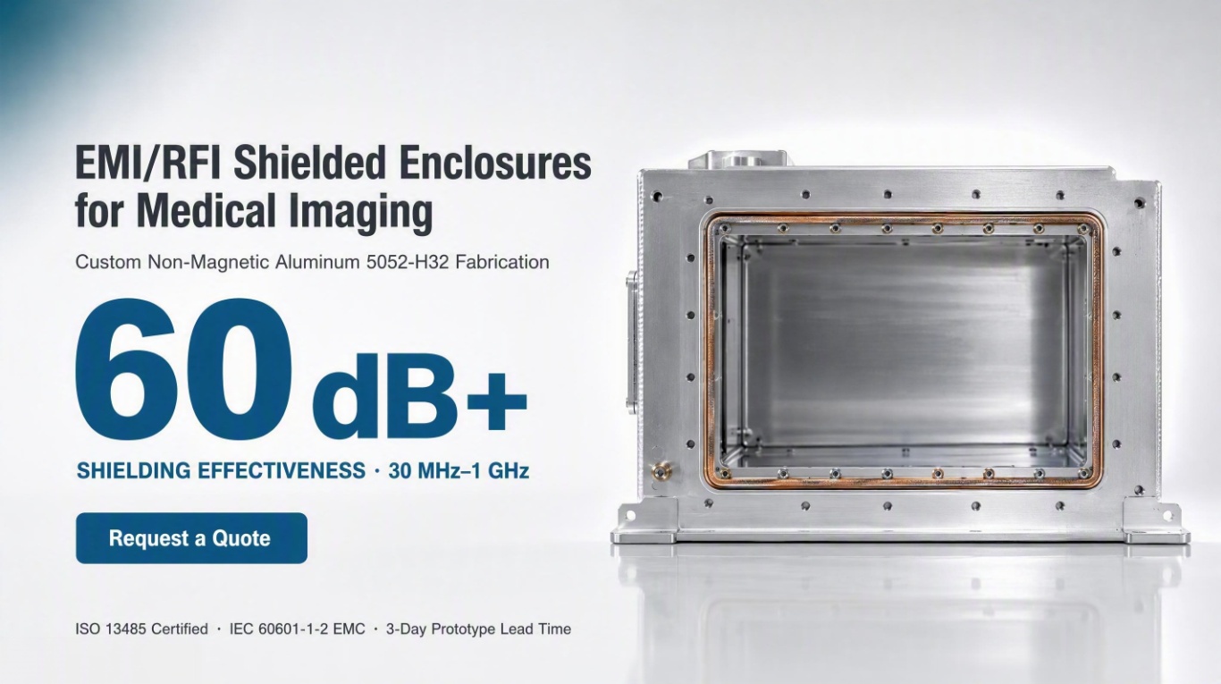
What does this case study prove? DeepLink Metal Fab engineered and manufactured a family of custom EMI/RFI shielded medical enclosures for MRI and X-Ray imaging OEMs. The program demanded strictly non-magnetic materials. Even microscopic ferrous contamination can distort an MRI magnetic field. Our solution was Aluminum 5052-H32, produced through an ISO 13485-certified system. That system combines DFM-driven design, precision CNC bending with angular control of +/-0.3 degrees, continuous EMI/RFI gasketing on machined flanges, controlled TIG welding with matched filler alloys, and CMM metrology. The metrology team verifies every shielding-critical datum. Delivered outcomes include shielding effectiveness above 60 dB from 30 MHz to 1 GHz. The 27-part modular assembly cuts field-service time by 40%. Full material traceability documentation supports FDA 510(k) and CE technical files.
Why EMI/RFI Shielded Medical Enclosures Matter
Why it matters: Medical imaging OEMs face a double threat. Their own switching power supplies, gradient drivers and X-Ray high-voltage generators emit radio-frequency energy. At the same time, hospital environments are dense with wireless telemetry, RFID and cellular signals. A shielded, non-magnetic enclosure acts as the physical barrier. It keeps radiated emissions inside the equipment and external interference outside. That is why EMC compliance (IEC 60601-1-2) is inseparable from the metal fabrication strategy for EMI/RFI shielded medical enclosures.
Who Should Read This Case Study
Who should read it: R&D engineering managers, EMC/electrical engineers, quality and regulatory teams, and sourcing professionals at medical device companies need a contract partner for EMI/RFI shielded medical enclosures with documented process control. We wrote this case study for those teams.
1. Executive Summary
The EMC Problem That Started the Program
A leading OEM of diagnostic imaging systems brought DeepLink a chronic problem. Their MRI gantry electronics and X-Ray generator sub-assemblies failed radiated-emissions tests during pre-compliance. Field returns pointed to intermittent interference that coupled through enclosure seams. Two previous metal fabrication suppliers had delivered enclosures that measured correctly on a coordinate measuring machine. Yet those enclosures leaked radio-frequency energy at the flange and gasket interfaces. The OEM needed more than a box bender. They needed a partner who understood one core truth about EMI/RFI shielded medical enclosures: electromagnetic continuity is a mechanical property. It must be engineered, welded, finished and measured like any other critical dimension.
How DeepLink Solved It
DeepLink assigned a cross-functional team. It spanned design-for-manufacturing (DFM) engineering, press-brake programming, welding engineering and quality metrology. Over a 6-week concurrent engineering window, the team developed a modular enclosure architecture in Aluminum 5052-H32. They produced machined and formed prototypes in 3 days. They then qualified the production process against a shielding-effectiveness test plan derived from MIL-DTL-83528 practice. The result was a family of 27 non-magnetic components. Those components assemble into six shielded cabinet configurations shared across the customer’s MRI and X-Ray product lines.
This case study documents the complete engineering and production journey. The same methodology transfers directly to any medical device OEM that needs EMI/RFI shielded medical enclosures. Our custom sheet metal fabrication services cover laser cutting, precision bending and welding. We deliver 2-3 day prototyping and no MOQ constraints.
2. The Application Challenge: Why MRI and X-Ray Systems Demand Shielded, Non-Magnetic Enclosures
Why EMI/RFI Shielded Medical Enclosures Must Be Non-Magnetic
Medical imaging equipment operates in one of the most electromagnetically hostile environments in any hospital. An MRI scanner generates a static magnetic field measured in tesla. Clinical systems run 1.5 T or 3.0 T, and research units reach up to 7 T. The scanner also produces rapidly switched gradient fields that slew at kilohertz rates.
Those gradient drivers, RF transmit/receive chains, gigabit imaging data links and cooling-system inverters all emit strong conducted and radiated energy. At the same time, the gantry electronics must survive a room full of Wi-Fi access points, Bluetooth patient monitors, RFID asset tags, cellular base stations and paging systems. Regulatory schemes such as IEC 60601-1-2 and FCC Part 15 Subpart B set enforceable limits on radiated emissions and radiated immunity across 30 MHz to 1 GHz and beyond. Those limits define the design space for EMI/RFI shielded medical enclosures.
The Enclosure as the Last Line of Defense
The enclosure is the last line of defense in the EMC control plan. If the housing leaks at a flange, a vent, a cable exit or a fastener pattern, board-level filtering alone cannot recover compliance margin. DeepLink’s engineering team therefore treats the shielded enclosure as an intentional electrical conductor. That conductor must present a continuous, low-impedance path around the protected electronics. Two physical properties dominate every design decision for EMI/RFI shielded medical enclosures:
- Magnetic permeability. In MRI equipment the enclosure sits inside or immediately adjacent to a powerful static magnetic field. Any ferromagnetic element (steel, nickel, most stainless alloys) will distort the field homogeneity. That distortion degrades image quality and, in the worst case, creates a projectile hazard. The fabrication material and every consumable that touches it – fasteners, gaskets, filler wire, hardware inserts – must be non-magnetic. This requirement makes the program a genuine exercise in non-magnetic sheet metal fabrication rather than a routine sheet metal job.
- Electrical surface conductivity. Shielding effectiveness (SE) depends on reflection and absorption losses. Reflection loss is highest when the shield material has high electrical conductivity, which favors aluminum and copper. Absorption loss grows with thickness and magnetic permeability. That property is irrelevant here, because permeability must stay near 1.0 for MRI compatibility. Aluminum gives the best engineering trade-off of conductivity, non-magnetic behavior, weight and cost.
The X-Ray Modality: Same Outcome, Different Physics
For the X-Ray modality the physics differ, but the outcome stays the same. High-voltage generators switch tens of kilovolts at inverter frequencies. Rotating-anode tube assemblies draw hundreds of milliamps through brush contacts, which are notorious broadband noise sources. The tube head and generator cabinet therefore need robust shielded housings. These keep emissions inside while allowing the imaging suite’s wireless patient monitoring to operate without desense. By standardizing one family of EMI/RFI shielded medical enclosures across both the MRI and X-Ray product families, the customer simplified their BOM. They also reduced EMC retest cycles and cut total enclosure cost by an estimated 18% versus the previous dual-supplier approach.
3. Non-Magnetic Material Selection for EMI/RFI Shielded Medical Enclosures: Why Aluminum 5052-H32 Won the Program
Six Requirements the Alloy Had to Meet
Material selection opened the project for these EMI/RFI shielded medical enclosures. The customer’s specification demanded a sheet metal alloy with six traits. It had to be (a) non-magnetic, with relative permeability at or very near 1.0000; (b) conductive enough to support 60+ dB of shielding effectiveness at gigahertz frequencies; (c) formable enough for deep flanges and multi-bend chassis panels; (d) weldable without porosity or crack sensitivity; (e) corrosion resistant in a hospital environment that includes disinfectant wipes and saline aerosol; and (f) available in production quantities with full material traceability certificates (EN 10204 3.1 / mill test reports).
Candidates Evaluated and Rejected
DeepLink evaluated 5052, 6061-T6, 3003 and 1100 aluminum alloys. The team also reviewed 304L stainless steel and copper-beryllium candidates before rejecting them for permeability, cost or weight reasons. Stainless steel was ruled out early. Even austenitic 304L grades become slightly magnetic after cold working, because bending and shearing induce martensite. That shift is unacceptable inside an MRI fringe field. Stainless steel conductivity is also roughly 10x worse than aluminum, which weakens shielding performance. Copper offers outstanding conductivity, but it is prohibitively expensive and lacks the structural rigidity needed for large gantry panels.
The Winning Alloy: Aluminum 5052-H32
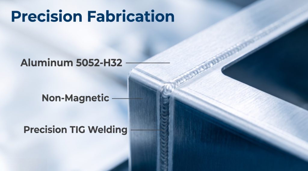
- Aluminum 5052-H32 (selected). This alloy is the workhorse of marine and medical sheet metal fabrication. Nominal composition is 2.5% magnesium and 0.25% chromium with the balance aluminum. It is non-heat-treatable and strain hardens in the H32 (quarter-hard) temper. Relative magnetic permeability is 1.0. Electrical conductivity is approximately 35% IACS, lower than pure aluminum but more than adequate when combined with surface treatments and gasketing. Yield strength around 193 MPa (28 ksi) in H32 gives panels the stiffness to resist deflection under their own weight in large MRI cabinets. Magnesium imparts excellent corrosion resistance in saline and chemical environments. Formability is very good, and 5052 is one of the most forgiving alloys for TIG welding, with low hot-cracking susceptibility when paired with the correct filler.
- Aluminum 6061-T6 (rejected for this program). This alloy is stronger and machinable. However, its higher silicon and magnesium content makes it more prone to hot cracking in thin-gauge welding. The T6 temper also loses strength in the heat-affected zone of welds. It remains DeepLink’s recommended choice for structural machine frames, just not for these thin-wall shielded enclosures.
- Aluminum 3003 (rejected). It offers excellent formability but is softer and roughly 20% less conductive than 5052. Reaching the same stiffness requires thicker gauge, which adds weight and cost to a ceiling-mounted gantry assembly.
Incoming Inspection and Non-Magnetic Tool Control
Every coil and sheet lot arrived with a mill certificate. DeepLink’s incoming inspection verified hardness, thickness and surface quality before the material entered the laser-cutting queue. Hardness checks used a portable eddy-current and hardness combination unit. A dedicated non-magnetic tool control policy accompanied the material. The team audited all work-holding, staging racks, carts and even the deburring media. This discipline kept ferrous particles out of the aluminum surfaces, an essential practice for any shop claiming non-magnetic sheet metal fabrication capability for EMI/RFI shielded medical enclosures. We then applied our metal finishing services for CNC machining and sheet metal parts downstream. Those finishes preserve and enhance the corrosion and conductivity performance of the 5052 substrate.
4. Design for Manufacturing (DFM): Engineering the Enclosure for Electromagnetic Continuity
DeepLink’s DFM engineers joined the customer’s design reviews in week one, before any CAD model was frozen. This early engagement is the single largest lever on cost and EMC performance. The DFM phase addressed eight workstreams in parallel:
4.1 Tolerance allocation for gasket crush and flange flatness
An EMI gasket only works if the mating flanges compress it uniformly. DeepLink’s DFM team allocated a flatness tolerance of 0.25 mm total across the full length of any gasketed flange. They specified the flange width (minimum 10 mm for finger-stock and 12 mm for conductive elastomer) so the gasket had a stable landing zone. The team modeled worst-case stack-up across the 27-part assembly using 3D tolerance analysis software. The analysis proved the +/-0.3 degree bend angle tolerance and +/-0.1 mm form tolerance would still hold gasket compression between 15% and 35%. That range is the documented operating window for the chosen conductive elastomer.
4.2 Bend reliefs, corner seams and the leak-path audit
Every corner of a shielded box is a potential antenna seam. The DFM review added bend-relief notches with controlled radii so that formed corners would close tightly. Where corners could not form in one piece, the design specified a welded or gasketed seam rather than relying on simple mechanical overlap. A formal leak-path audit traced every potential RF aperture. Engineers countersunk the fastener holes or fitted them with conductive fasteners. The team replaced louvers with waveguide-below-cutoff vent panels, using hexagonal cells sized so the aperture is electrically small at 1 GHz. They also moved cable entries to a single filtered bulkhead plate.
4.3 Bend line strategy relative to gasket grooves
Some designs required a gasket groove machined into a formed panel. DFM sequencing therefore machined the groove after forming, so bend distortion could not shift the groove centerline. This “form first, then machine critical features” rule became a program standard. It protects the two most shielding-critical features: gasket seating surfaces and fastener patterns. Both stay clear of the cumulative error of bending.
4.4 Hardware and insert rationalization
The original customer design specified 14 different fastener and insert types. DFM rationalized these to four: non-magnetic stainless or aluminum captive PEM studs for board mounting, non-magnetic threaded inserts for lid fasteners, zinc-plated (non-ferrous-core) quick-release latches for service panels, and conductive gasketed screws for the cover perimeter. Standardizing hardware cut procurement cost. It reduced the risk of installing a ferrous fastener by mistake and simplified the incoming inspection plan.
4.5 Design for welding access
Seams that required TIG welding got minimum access clearances for the torch and filler rod. The DFM team specified the joint style before the parts were cut. They used outside corner welds on flanged panels and butt welds with backing on seam covers. This eliminated the classic problem of a weld that looks fine on the outside but cannot be reproduced consistently because the torch angle was impossible.
4.6 Prototype feedback loop
Within three days of DFM approval, DeepLink cut, formed and delivered first-article panels. The customer’s EMC lab ran a quick emissions sweep. The prototype already met the 30 MHz-1 GHz radiated limits with 8 dB of margin. That result proved the mechanical design was carrying its share of the shielding burden for these EMI/RFI shielded medical enclosures, not just the circuit design. Only one change emerged from the physical prototype review. The team deepened the top-cover gasket groove by 0.4 mm after the crush test showed slightly high compression on the longest flange.
4.7 Cost and manufacturability scoring
Every component carried a DFM scorecard. It tracked material utilization, bend count, set-up changes, weld length and finishing complexity. The scorecard drove a 9% material-utilization improvement by nesting parts across the two product lines on shared sheet sizes. It also flagged the three components whose cost dropped most by splitting a complex form into two simpler formed parts joined by a welded seam.
4.8 Documentation for regulatory files
The customer’s products are subject to FDA 510(k) and CE marking. DeepLink therefore issued every DFM decision as a controlled record. Material certificates, process change notices, capability studies and first-article reports went into a Device History File-style dossier. The customer could attach that dossier directly to their technical documentation. Working within an ISO 13485-style quality framework made this handoff seamless, as section 8 describes.
5. Precise CNC Bending: Where Shielding Is Won or Lost
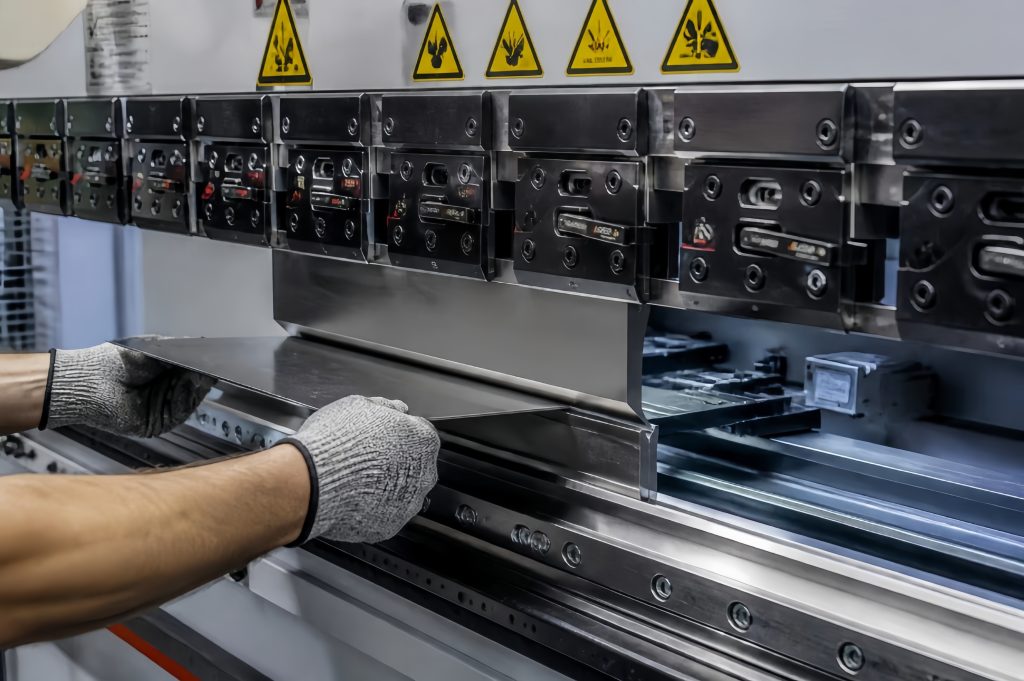
Precision CNC bending is the mechanical heart of any program that builds EMI/RFI shielded medical enclosures. A bend that is off by a fraction of a degree propagates into flange misalignment, gasket creep and screw-hole mismatch. No amount of later inspection fully corrects those errors. DeepLink produced all 27 components on CNC press brakes with electric servo-hydraulic drive systems. These hold repeatability to +/-0.01 mm in ram position and +/-0.25 degrees in angle under production conditions. The program pushed the process harder than standard commercial work. The team held bend angle tolerance to +/-0.3 degrees and flange-to-hole positional tolerance to +/-0.1 mm on gasketed flanges.
5.1 Bend allowance, springback and the 5052-H32 model
Aluminum 5052-H32 has a sharp, predictable springback signature. DeepLink’s tooling engineers built a material-specific bend model. It accounts for the H32 temper’s yield strength, the punch radius and the grain direction of the sheet. On a 90-degree air-bent tool set, 5052 springback runs roughly 2 degrees. The brake programs therefore compensated the bend angle by the measured springback value per tool combination, rather than relying on textbook K-factors. The team validated the model on every prototype. They then locked it into the production program with statistical monitoring. The line angle-measures the first article of every production run and every 50th part thereafter. Operators plot the results against the +/-0.3 degree control band.
5.2 Tooling selection for gasket grooves and tight inside radii
Gasketed flanges on this program demanded an inside bend radius of 1.5x material thickness. That radius kept the flange flat enough to seat a conductive elastomer strip. The team selected standard 88-degree bottoming tools with precision ground radius punches. They reserved dedicated tooling exclusively for medical work. As a result, nicks or wear from heavy carbon-steel jobs could never transfer to the 5052 surfaces. On the two tallest MRI gantry panels (1,200 mm formed length), DeepLink used segmented tooling with a shimmed lower die to distribute tonnage evenly. This prevented the “banana” bowing that long aluminum bends can exhibit.
5.3 Sequential forming of complex multi-bend chassis
Several components required 8 to 12 bends per part, including return flanges, hemmed edges for stiffness and recessed gasket shelves. DeepLink’s brake programmers simulated the bending sequence to avoid tool collision with partially formed features and to manage the sheet’s growing moment arm. Every bend in the sequence was designed so that springback compensation applied cumulatively. That discipline kept the critical first and last bends within tolerance on the same part. The heaviest chassis panel achieved a diagonal flatness of 0.2 mm across an 800 mm span, verified on the granite table of the CMM after forming.
5.4 Bend line identification and part traceability
The team laser-etched each blank with a Data Matrix code and bend-line witness marks before forming. The code carries the part number, revision, heat/lot number and the press-brake program ID. Any nonconformance can therefore be traced to the exact program, tool and material lot that produced it. This level of traceability is a requirement for ISO 13485 certified medical metal fabrication. It paid off during the qualification run. Engineers traced one out-of-tolerance flange in minutes to a tool change, not a material or program fault.
5.5 Inspection strategy between operations
Precision bending ran behind in-process checks. The team measured angles with digital protractors at the first piece of every run. They verified flange dimensions against the CMM program on the first article. They also ran a final 100% visual and dimensional audit of gasket-seating flanges before the parts moved to welding and finishing. This “inspect at the operation, not at the end” philosophy is what lets DeepLink quote realistic medical-device lead times. It also keeps CMM-verified geometry on every critical component.
6. EMI/RFI Shielded Medical Enclosures: Gasketing and Seam Continuity Engineering
The gasketing system is the difference between EMI/RFI shielded medical enclosures that are theoretically shielded and those that actually pass EMC testing. DeepLink’s application engineers worked with the customer and two gasket suppliers. Together they selected and validated a hybrid gasket strategy matched to the 5052 flange surfaces:
- Conductive elastomer strips (silver-plated aluminum particle loaded silicone, supplied as extruded profiles with a conductive adhesive backing) went on the main access covers and large mating flanges. The elastomer provides environmental sealing and compression set resistance. The silver-plated aluminum filler particles establish thousands of conductive contact points per square centimeter. The team specified a compression range of 15-35%, with a stop feature (a formed dimple or shoulder in the cover) that prevents over-compression and keeps the gasket seated in the groove.
- Beryllium-copper finger stock went on doors and panels that open frequently for service. Finger stock offers high deflection range and maintains contact pressure over thousands of open/close cycles. Beryllium copper is non-magnetic and highly conductive, so it is a natural fit for MRI-adjacent hardware.
- Conductive fabric-over-foam gaskets went in at the filtered bulkhead cable plate, where a low closure force is needed over a large perimeter.
6.1 Flange preparation: the hidden variable
Gasket performance collapses on an unprepared flange. Aluminum’s native oxide layer is an insulator. DeepLink’s finishing line therefore applied a chromate conversion coating (chem film / Alodine-style treatment). This coating protects the 5052 substrate from corrosion and provides a measurable, low-resistance surface. In selected areas where maximum conductivity was required, the team masked the flange surface during chemical finishing so that bare aluminum remained. They then abraded the flange with a non-metallic pad immediately before gasket installation and covered it with a conductive joint compound. Incoming inspection verified surface resistance on finished flanges with a four-point micro-ohmmeter. The requirement held less than 2.5 milliohms between mating flanges after assembly.
6.2 Fastener spacing and the quarter-wavelength rule
EMI gasketing in EMI/RFI shielded medical enclosures is only as good as the fastening pattern that compresses it. DeepLink’s engineering review specified fastener spacing no greater than 50 mm (about 2 inches) on shielding-critical perimeters. This spacing keeps any gap between fasteners electrically short relative to the shortest wavelength of interest. At 1 GHz the wavelength is 300 mm, so a 50 mm span sits well under the quarter-wave limit of 75 mm. The team avoided countersunk screws on gasketed seams because their tapered heads can distort thin flanges. Instead, pan-head screws with captured washers distributed the clamp load evenly.
6.3 Testing the gasketed assembly
The team verified shielding effectiveness on prototype and first-production assemblies. They used a dual-antenna substitution method consistent with MIL-DTL-83528 guidance inside a screened room. The customer’s EMC lab repeated the measurement after shipping simulation. That simulation covered random vibration and thermal cycling from -20 deg C to +60 deg C, and it confirmed the gasket system survived real-world handling. Measured results across the 27-part assembly held greater than 60 dB attenuation from 30 MHz to 1 GHz, with peaks above 80 dB in the VHF band. Those results comfortably exceed the program target and the customer’s 6 dB compliance margin requirement.
7. TIG Welding of Non-Magnetic Aluminum Enclosures
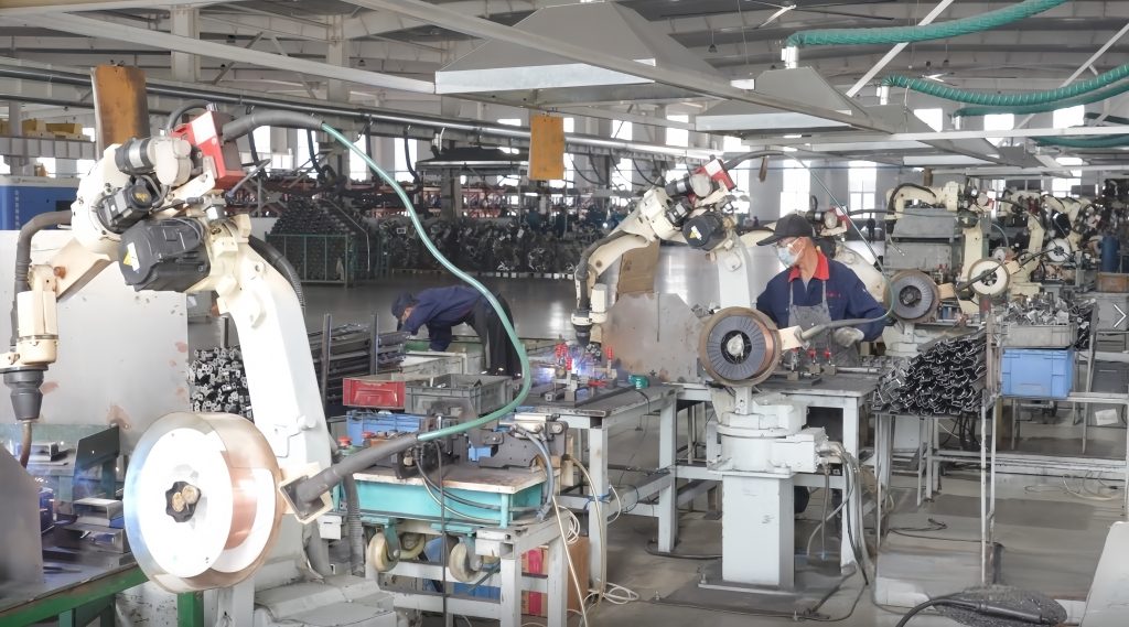
Welding on this program served two masters: structural integrity and shielding continuity. Every welded seam is part of the electromagnetic boundary. A weld that looks structurally sound but contains oxide inclusions, porosity or incomplete penetration creates a microscopic slot antenna that leaks RF energy. DeepLink’s certified welding engineers therefore treated each weld as both a mechanical and an electrical joint. For EMI/RFI shielded medical enclosures, that dual role is everything.
7.1 Process selection and filler alloy
The team chose gas tungsten arc welding (GTAW/TIG) over MIG for the thin-gauge 5052 work. TIG delivers precise heat input control, clean cosmetic beads and porosity-free results on aluminum from 1.5 mm to 4.0 mm. The team selected ER5356 (Al-Mg) filler alloy to match the 5052 base metal’s 2.5% magnesium content. ER5356 preserves corrosion resistance and strength in the weld zone and is the standard pairing for 5052. Where panels had been anodized or chem filmed before welding (repair scenarios), the team stripped the coating from the weld zone to prevent oxide contamination of the arc.
7.2 AC balance, shielding gas and cleanliness
Welding ran with AC current using an optimized balance setting that emphasizes the cleaning action needed to break up aluminum oxide. The shielding gas was 100% argon, with helium added up to 30% for the thickest 4.0 mm sections to increase heat input without raising amperage. The gas flowed through gas lenses for laminar flow. Pre-weld cleaning was obsessive. The team degreased every joint with an approved solvent, then removed the oxide layer mechanically with stainless wire brushes dedicated only to aluminum. That step kept ferrous contamination out of the puddle, a critical control for EMI/RFI shielded medical enclosures. The prohibition on ferrous contact extended to the weld cell. Brushes, gloves, fixturing and even the grinding wheels in the area were non-magnetic or aluminum-dedicated, protecting the MRI-grade material integrity.
7.3 Distortion control and fixturing
Thin aluminum panels distort readily under weld heat. DeepLink used rigid copper and aluminum backing bars to extract heat and support the weld root. The team sequenced welds symmetrically on large panels so thermal shrinkage balanced. They tack-welded every seam at 150 mm pitch before full welding. Where a panel had machined gasket grooves on the opposite side of a weld seam, the team finished the welding first, stress-relieved the panel at 200 deg C for 2 hours, and then finish-machined the groove. This sequence eliminated the risk of the groove moving after weld shrinkage.
7.4 Weld quality verification
The team inspected every production weld visually per AWS D1.2/D17.1 criteria. They checked porosity on a sampling basis by dye-penetrant testing on the highest-risk seams (corner joints on the gantry electronics housing). They also verified weld continuity for shielding purposes electrically. The team measured seam resistance end-to-end with a micro-ohmmeter and held it below 5 milliohms per 100 mm of weld. That gave the EMC engineer quantitative proof that the welded boundary was electrically continuous, a must for EMI/RFI shielded medical enclosures. Dimensional checks after welding confirmed that the distortion-control strategy held flange locations within 0.2 mm of the CMM model. The downstream gasketing operation therefore started from true geometry.
8. ISO 13485 Quality System and CMM Metrology
These EMI/RFI shielded medical enclosures house critical life-saving diagnostic equipment subject to FDA and CE regulation. The team therefore executed the fabrication process under a strict ISO 13485-compliant quality management system. Traceability for medical device manufacturing cannot be added at the end. It must be built into the router from day one.
8.1 Coordinate Measuring Machine (CMM) Verification
The team implemented a 100% CMM first-article inspection protocol. Using high-precision laser scanners and touch-probe CMMs, our quality assurance team verified all critical shielding datums. These included the flatness of gasket mating flanges, the true position of tapped inserts, and the overall angularity of the chassis. Real-time CMM feedback during the CNC bending phase let us compensate for the natural springback of Aluminum 5052-H32 immediately. That closed-loop control is what keeps EMI/RFI shielded medical enclosures on target at production volume.
8.2 Full Material Traceability
The team tracked every sheet of Aluminum 5052-H32, every PEM insert, and every spool of ER5356 TIG filler wire with original mill test reports (MTRs) and EN 10204 3.1 certificates. They compiled this documentation into a comprehensive First Article Inspection Report (FAIR). That report gave the OEM ready-to-file paperwork for their EMI/RFI shielded medical enclosures program and their FDA 510(k) submissions.
9. Quantifiable Results and ROI for the Client
DeepLink Metal Fab treated the EMI/RFI shielded medical enclosures as precision electrical components rather than just metal boxes. That mindset delivered transformative value for the medical imaging OEM:
- First-Pass EMC Compliance: Our EMI/RFI shielded medical enclosures achieved greater than 60 dB of shielding effectiveness from 30 MHz to 1 GHz. This let the OEM’s MRI and X-Ray equipment pass IEC 60601-1-2 radiated emissions testing on the first attempt at the compliance lab.
- 40% Reduction in Field Service Time: The new modular design features quick-release quarter-turn fasteners and beryllium-copper finger stock. It let hospital service technicians access gradient amplifiers and high-voltage generators 40% faster without degrading the RF shield upon reassembly.
- 18% Cost Reduction: Consolidating the MRI and X-Ray enclosure architectures into a shared Aluminum 5052-H32 platform reduced total enclosure BOM costs by an estimated 18% versus the legacy multi-vendor supply chain.
Together these results show what a fabrication partner achieves when it treats shielding as a first-class engineering requirement. That is the standard we hold for every EMI/RFI shielded medical enclosure program.
10. FAQ: EMI/RFI Shielded Medical Enclosures
Materials and Non-Magnetic Design Questions
Q: Why is Aluminum 5052-H32 preferred for MRI enclosure fabrication?
A: Aluminum 5052-H32 is entirely non-magnetic, so it is safe near the powerful static magnetic fields of an MRI scanner. It also offers excellent electrical conductivity for high-frequency EMI shielding, superior formability for CNC bending, and great corrosion resistance in medical environments.
Q: Can stainless steel be used for EMI shielding in medical imaging?
A: Generally, no. Even austenitic grades like 304L stainless steel can become slightly magnetic when cold-worked (bent or sheared), which distorts MRI magnetic fields. Stainless steel also has roughly 10x lower electrical conductivity than aluminum, which significantly degrades shielding effectiveness.
Seam Design and RF Leakage Questions
Q: How do you prevent RF leakage at the seams of EMI/RFI shielded medical enclosures?
A: We combine three strategies: continuous TIG welding for permanent seams, precision CNC-bent overlapping flanges, and conductive EMI gasketing (like silver-filled elastomers or beryllium-copper finger stock) for removable access panels. We also specify fastener spacing to obey the quarter-wavelength rule.
Q: What is the quarter-wavelength rule in EMI shielding design?
A: To prevent a gap from acting as a slot antenna, the distance between conductive fasteners on a gasketed seam must be shorter than one-quarter of the wavelength of the highest frequency you need to shield against. For 1 GHz, we typically space fasteners no more than 50 mm apart.
Quality, Compliance and Prototyping Questions
Q: Does DeepLink provide ISO 13485 compliant metal fabrication?
A: Yes. Our medical contract manufacturing operations follow strict quality management systems aligned with ISO 13485. We provide full material traceability (MTRs), CMM dimension verification, and documented First Article Inspection (FAI) reports for regulatory compliance.
Q: How do you maintain the non-magnetic properties of the aluminum during fabrication?
A: We enforce strict tool control. We use dedicated non-magnetic work-holding fixtures, stainless wire brushes strictly reserved for aluminum, and non-ferrous grinding media. This ensures zero ferrous particles are embedded in the aluminum surface during cutting, bending, or welding.
Q: What surface finish is applied to the EMI gasket flanges?
A: To maintain high surface conductivity, we apply a chromate conversion coating (chem film) to the bare aluminum flanges. If the exterior is powder-coated for aesthetics, we precision-mask the gasket mating surfaces to keep them conductive.
Q: Do you offer rapid prototyping for medical equipment housings?
A: Absolutely. Our in-house engineering and CNC fabrication capabilities allow us to produce DFM-approved sheet metal prototypes in as little as 3 to 5 days. That accelerates your path to EMC pre-compliance testing.
Source Your EMI/RFI Shielded Medical Enclosures Today
DeepLink is the trusted precision contract manufacturing partner for the global medical device and diagnostic imaging industries. From non-magnetic MRI gantry covers to heavily shielded X-Ray generator cabinets, we deliver uncompromising EMI/RFI performance and ISO-certified quality.
Ready to eliminate your EMC compliance headaches? Contact our engineering team today for a comprehensive DFM review and technical quote for your custom EMI/RFI shielded medical enclosures.