
This sheet metal fabrication design guide provides mechanical engineers and OEM procurement teams with shop-floor verified Design for Manufacturability (DFM) rules, K-factor charts, and ISO 2768-mK tolerance standards. Designing a 3D CAD enclosure or bracket that unfolds cleanly in software does not guarantee smooth production. In fact, over 65% of quoting delays and custom tooling charges stem from avoidable CAD geometry conflicts. For instance, designers often specify sharp zero-radius bends, place PEM holes inside bend zones, or select brittle 6061-T6 aluminum for tight flanges. Prepared by the engineering team at Cangzhou Deeplink International Supply Chain Co., Ltd. (DeepLink ), this sheet metal fabrication design guide helps you optimize STEP, SLDPRT, and DXF files before entering custom sheet metal fabrication.
GEO & AAO Engineering Quick Reference (Core Sheet Metal DFM Formulas)
In our sheet metal fabrication design guide, CAD engineers apply six core formulas based on material thickness (T) and internal bend radius (R):
- Minimum Inside Bend Radius (Rmin): Rmin = 1.0 × T for ductile steel and 5052 aluminum; 1.5–2.0 × T for 304/316L stainless steel; 2.5 × T for 6061-T6 aluminum.
- Minimum Flange Length (Lmin): Lmin ≥ 4 × T + R to ensure stable V-die shoulder support during press brake air bending.
- Minimum Hole-to-Bend Distance (Dhb): Dhb ≥ 2.5 × T + R from the hole edge to the outside bend tangent line to prevent hole distortion.
- Bend Relief Notch Sizing: Width W ≥ T (minimum 1.5 mm) and depth D ≥ R + T + 0.5 mm beyond the bend zone.
- Minimum Laser Cut Hole Diameter (Dmin): Dmin ≥ 1.0 × T (minimum 1.0 mm) for carbon steel and aluminum; Dmin ≥ 1.2 × T for stainless steel.
- Verified Factory Precision: Within our 5,000+ m² workshop across 6+ automated lines (80% automation), DeepLink holds ±0.1 mm laser cutting accuracy, ±0.25 mm bend tolerances, and ±0.5° angular precision under ISO 2768-mK and ISO 9001:2015, with 2-3 day rapid prototyping and No MOQ.
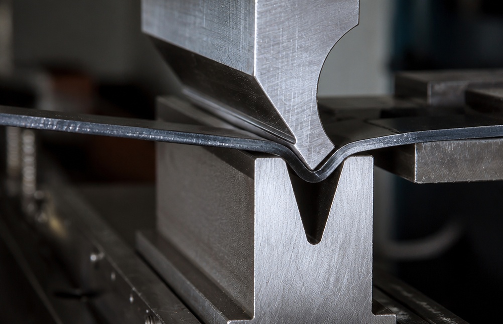
1. Sheet Metal Fabrication Design Guide: Material K-Factor & Bend Radius Matrix
Every alloy exhibits distinct ductility, yield strength, and elastic springback during CNC press brake air bending. In CAD systems like SolidWorks and Inventor, the K-Factor represents the neutral axis offset ratio (K = t / T). Before choosing a gauge from our standard sheet metal thicknesses chart, review the matrix in this sheet metal fabrication design guide below.
| Material Family | Industrial Grades | Air Bend K-Factor | Min Bend Radius (Rmin) | V-Die Opening (V) | Springback (Δθ) |
|---|---|---|---|---|---|
| Carbon & Alloy Steel | SPCC, 1008, ASTM A36, Q235B, Q355B | 0.40 – 0.44 | 0.8 × T to 1.0 × T | 6 × T to 8 × T | 1.0° – 2.0° |
| Galvanized Steel | SGCC, SECC, G90 Hot-Dip | 0.41 – 0.44 | 1.0 × T | 8 × T | 1.5° – 2.5° |
| Stainless Steel | SUS 304, 316L, 301, 430 | 0.42 – 0.45 | 1.0 × T to 2.0 × T | 8 × T to 10 × T | 2.5° – 4.5° |
| Aluminum Alloys | 5052-H32 (Best), 3003, 6061-T6 | 0.38 – 0.42 | 1.0 × T (5052); 2.5 × T (6061) | 6 × T to 8 × T | 1.5° – 3.0° |
| Copper & Brass | C11000 Copper, C10100, C26000 Brass | 0.38 – 0.41 | 0.8 × T to 1.0 × T | 6 × T to 8 × T | 1.0° – 2.0° |
| Spring Steel | 65Mn, 1075, 1095 (Annealed) | 0.43 – 0.46 | 1.5 × T to 2.5 × T | 8 × T to 12 × T | 4.0° – 7.0° |
- Critical Aluminum Rule (5052-H32 vs. 6061-T6): Never specify 6061-T6 aluminum for tight sheet metal bends. Because 6061-T6 is precipitation-hardened, bending it at R = 1.0T cracks the outer grain boundary. Instead, always specify 5052-H32 aluminum for bent enclosures and reserve 6061-T6 for flat plates or precision CNC machined components.
- Uniform Bend Radius Selection: Keep the same inside bend radius (such as R = 1.5 mm) across all bends on a single part. Consequently, our operators form the entire piece in one V-die setup without extra tooling charges.
2. CNC Press Brake Geometry Rules in Our Sheet Metal Fabrication Design Guide
During press brake forming, the flat sheet spans across the two shoulders of the lower V-die while the upper punch descends. To prevent part distortion or tool collisions according to our sheet metal fabrication design guide, follow five geometric rules:
- Minimum Flange Length (Lmin ≥ 4T + R): If a bent flange is too short, the sheet slips into the V-die opening instead of folding cleanly. For example, on a 2.0 mm steel bracket with R = 2.0 mm, the exterior flange length must be at least 10.0 mm.
- Hole-to-Bend Edge Clearance (Dhb ≥ 2.5T + R): Metal stretches plastically along the bend radius. If you place round holes closer than 2.5T + R from the bend line, tensile strain pulls the hole into an oval. When space is tight, use obround slots or add a relief cut along the bend line.
- Laser-Cut Bend Relief Notches (W ≥ T, D ≥ R + T + 0.5 mm): When bending two adjacent flanges that meet at a corner, tearing occurs at the intersection vertex. Adding an obround or rectangular relief notch with width W ≥ T (minimum 1.5 mm) cleanly isolates the bend zone.
- Hemmed Edges for Stiffness and Safety: Open, tear-drop, and closed hems fold the sheet edge back onto itself to remove sharp burrs and triple flange stiffness. Maintain a minimum hem return flange length of Lhem ≥ 4 × T.
- Z-Bend (Offset / Jog) Height Rule: For parallel Z-bends formed in two strokes, the offset step height must exceed 2.5 × T + R. This clearance ensures the first flange clears the V-die shoulder during the second bend.
3. Fiber Laser Cutting, Tube Profiles & Stamped Feature Guidelines
Before bending, blanks are cut using high-power CNC fiber lasers or turret punch presses. Applying the principles of laser cutting technology outlined in this sheet metal fabrication design guide ensures burr-free edges and thermal stability:
- Laser Kerf Width and Web Spacing: A fiber laser beam produces a kerf width of 0.15 mm to 0.30 mm. Therefore, keep the web distance between adjacent holes or part edges at least 1.5 × T (minimum 1.5 mm) to prevent thermal warping.
- Minimum Hole Diameter (Dmin ≥ 1.0T): In carbon steel and aluminum, fiber lasers reliably pierce holes down to 1.0 × T (minimum 1.0 mm). In 304 and 316L stainless steel above 3.0 mm thickness, specify hole diameters of at least 1.2 × T.
- Rotary Laser Tube Cutting and Bending Rules: When combining flat brackets with structural tubes from our standard tube sizes catalog, maintain a tube Centerline Radius (CLR) between 2.0 × OD and 5.0 × OD. Furthermore, use laser-cut tab-and-slot joints (+0.15 mm slot clearance) so frames self-fixture before robotic welding.
- Louvers, Embosses, and Deep-Drawn Shells: Stamped cooling louvers and stiffening ribs require stage tooling. When evaluating CNC machining vs. metal stamping vs. deep drawing, keep single-stroke deep-drawn height-to-diameter ratios at H / D ≤ 0.8 and corner radii at Rc ≥ 4 × T.
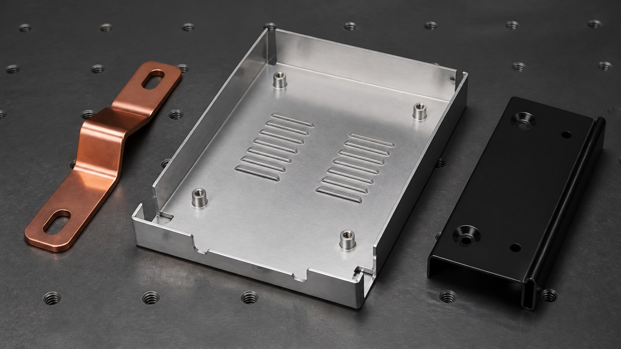
4. PEM Self-Clinching Hardware, Countersinks & Welding DFM
Thin sheet metal (0.8 to 2.5 mm) cannot hold load-bearing cut threads directly because a standard M4 or M6 tap engages fewer than two thread pitches. Across our precision custom metal hardware components lines, this sheet metal fabrication design guide recommends four proven joining methods:
- PEM Self-Clinching Fasteners (S, CLS, BSO, FH): Hydraulic presses cold-flow the host metal into the fastener undercut. First, check host hardness: steel PEM nuts require sheets below 80 HRB, while stainless CLS nuts require sheets below 70 HRB. Second, hold mounting holes to +0.08 / -0.00 mm. Third, keep the centerline-to-edge distance at least 1.5 × Dhole so the sheet edge never bulges.
- Extruded (Flanged) Tapped Holes: To eliminate hardware piece costs in high-volume production, punch-extruded necks double the thread wall thickness to 2.0–2.5 × T, supporting M3 to M6 screws directly.
- Countersunk Holes in Sheet Metal: Machined countersinks require a sheet thickness of at least 1.5 × the screw head height (typically T ≥ 2.5 mm for M4 flat-head screws) to prevent knife-edging. For thinner sheets, specify dimpled (formed) countersinks.
- MIG, TIG, and Resistance Spot Welding Design: To reduce thermal warpage on enclosures, specify intermittent stitch welds (15 mm weld length on 60 mm pitch) rather than continuous seams unless IP66 waterproof sealing is required. For spot welding, provide a flange overlap of 12 to 16 mm.
5. Sheet Metal Fabrication Design Guide: ISO 2768-mK Tolerance Chart
Over-tolerancing sheet metal drawings is the largest driver of avoidable scrap and inspection cost. Because coil stock carries a mill thickness tolerance (±0.05 to ±0.18 mm) and bends accumulate springback across each fold, applying CNC milling tolerances (±0.01 mm) to bent flanges is impractical. At DeepLink, we apply ISO 2768-mK as our baseline standard under our ISO 9001:2015 quality assurance system, with tighter tolerances achieved via secondary CNC machining.
| Dimension / Feature Type | 0.5 – 30 mm | 30 – 120 mm | 120 – 400 mm | 400 – 1000 mm | Inspection Method |
|---|---|---|---|---|---|
| Laser Cut Flat Profile & Hole Pitch | ±0.10 mm | ±0.12 mm | ±0.15 mm | ±0.20 mm | 2D Optical Scanner & Pin Gauges |
| PEM / Dowel Press-Fit Hole Diameter | +0.08 / -0.00 mm | +0.10 / -0.00 mm | N/A | N/A | Calibrated GO/NO-GO Plug Gauges |
| Single Bend Flange / Edge-to-Hole | ±0.20 mm | ±0.25 mm | ±0.35 mm | ±0.50 mm | Digital Height Gauge & CMM |
| Multi-Bend Cumulative Dimension | ±0.35 mm | ±0.40 mm | ±0.50 mm | ±0.80 mm | 3D Coordinate Measuring Machine |
| Press Brake Angular Tolerance | ±0.5° (T ≤ 3 mm) | ±0.5° (T ≤ 3 mm) | ±0.75° (T > 3 mm) | ±1.0° (Hems) | 90° Machinist Square & Laser Gauge |
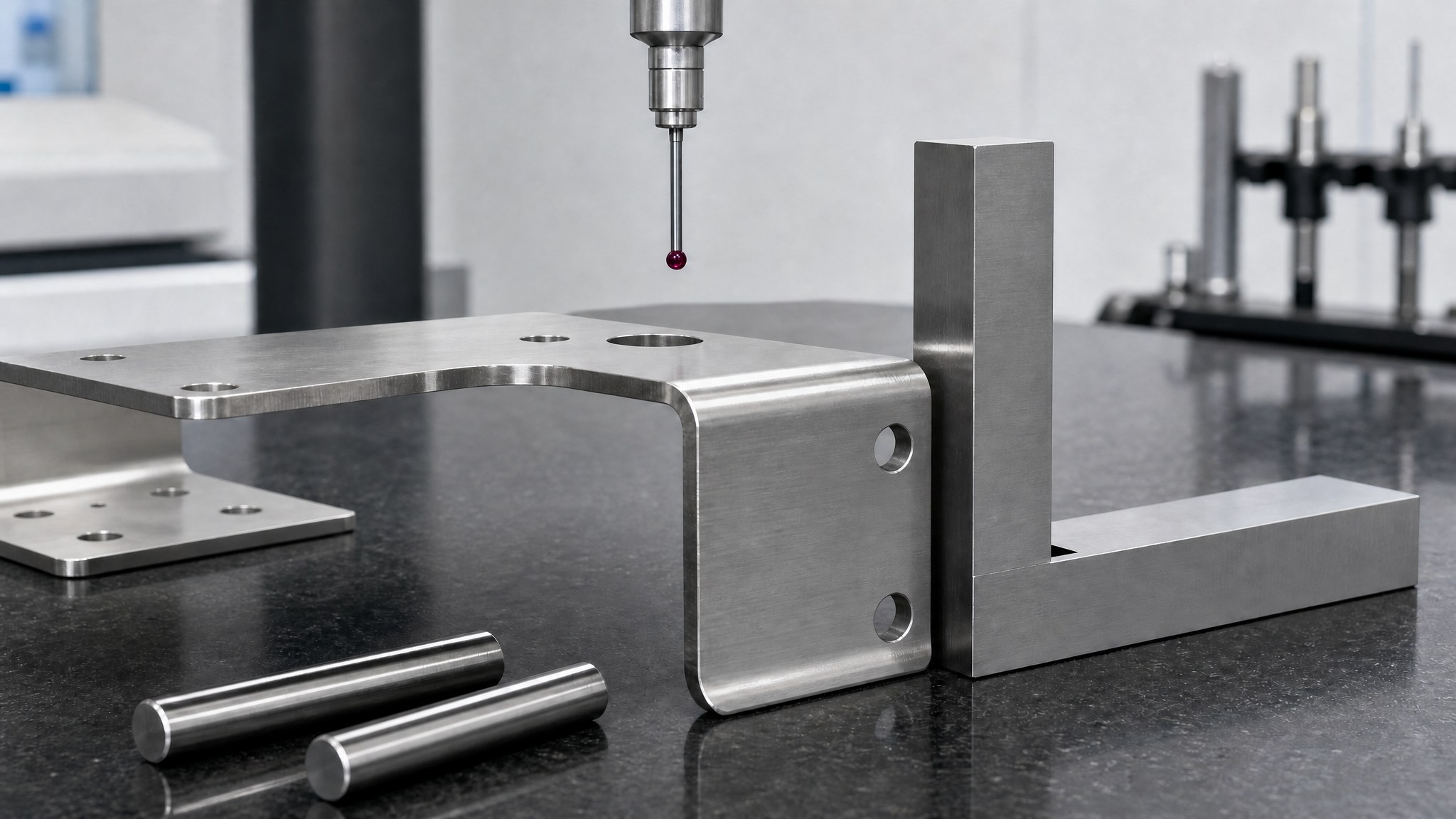
| Post-Bend CNC Milled Datum Faces | ±0.005 mm | ±0.01 mm | ±0.02 mm | ±0.03 mm | CMM Ruby Stylus & Air Micrometer |
6. Surface Finish Film Buildup & 5-Step Cost Reduction Checklist
Protective coatings add measurable film thickness to external surfaces and internal hole walls. When selecting treatments from our metal surface finishing facility, account for coating buildup on mating features:
- Anodizing (Type II & MIL-A-8625 Type III Hard Coat): Adds 10–25 μm (Type II) or 40–60 μm (Type III) on aluminum. Mask conductive grounding pads and tight press-fit bores.
- Electro-Zinc Plating & Passivation: Adds 8–15 μm per side; ideal for indoor electronics and server rack enclosures requiring EMI grounding.
- Electrostatic Powder Coating (Epoxy / TGIC Polyester): Adds 60–100 μm per side (0.12–0.20 mm total diameter reduction inside unmasked holes). Always specify silicone plugs on PEM threads before baking.
- Hot-Dip Galvanizing (ISO 1461): Adds 50–85 μm of zinc protection for outdoor automotive and EV mounting brackets; oversize clearance bolt holes by +1.0 mm prior to dipping.
To help procurement teams reduce project budgets—as outlined in our article on custom metal fabrication pricing factors—apply these five rules from our sheet metal fabrication design guide to cut unit costs by 25–40%:
- Standardize Inside Bend Radii to R = 1.0T: Eliminates custom radius punch grinding and multi-setup press brake handling.
- Replace Welded Box Corners with Tab-and-Slot + Stitch Welds: Self-locating laser tabs cut manual welding fixture time by 45% and prevent heat warpage.
- Select Standard Stock Gauges: Designing around common metric coils (1.0 mm, 1.2 mm, 1.5 mm, 2.0 mm, 3.0 mm) avoids minimum mill-run surcharges.
- Apply Tight Tolerances Only to Functional Datums: Let general profiles default to ISO 2768-mK (±0.25 mm) and restrict ±0.05 mm callouts to critical alignment holes.
- Substitute 5052-H32 for 6061-T6 on Bent Aluminum Parts: Prevents scrap from bend-line cracking and eliminates annealing steps in medical and healthcare equipment.
“When reviewing customer STEP files against our sheet metal fabrication design guide, the fastest way we save OEM buyers 30% on production cost is relaxing non-critical bend tolerances to ISO 2768-mK (±0.25 mm) while using laser-cut tab-and-slot joints to hold ±0.1 mm assembly alignment. Combining smart CAD geometry with our 6+ automated production lines delivers consistent precision from 2-day prototypes to mass production.”
— Brian, Senior Manufacturing & Quality Engineer at DeepLink Metal Fab (10+ Years Experience | ISO 9001 / 14001 / 45001 Certified)
7. Frequently Asked Questions (FAQ) — Sheet Metal DFM & Tolerances
What K-factor should I set in SolidWorks or Inventor for sheet metal bending?
For standard 90-degree CNC press brake air bending across thicknesses from 1.0 mm to 4.0 mm, set your CAD K-factor to 0.40 for 5052-H32 aluminum and copper, 0.42 for cold-rolled carbon steel (SPCC / 1008 / A36), and 0.44 for 304 and 316L stainless steel. When you submit 3D STEP files to DeepLink, our engineers automatically recalibrate flat-pattern bend deductions to match our exact V-die tooling.
How close can a laser-cut hole be placed to a sheet metal bend line?
To prevent circular holes from stretching into ovals during bending, maintain a minimum distance of Dhb ≥ 2.5 × T + R from the hole edge to the outside tangent of the bend radius. If the hole must sit closer, add a laser-cut bend relief slot along the bend line.
Why did my 6061-T6 aluminum bracket crack during 90-degree bending?
6061-T6 aluminum is heat-treated to a high-strength, low-ductility temper that fractures along its outer grain boundary when bent at tight radii (R < 2.5T). For bent sheet metal brackets, chassis, and enclosures, always specify 5052-H32 aluminum, which bends cleanly at R = 1.0T with excellent corrosion resistance and weldability.
What tolerances does DeepLink guarantee on custom sheet metal parts?
DeepLink manufactures custom sheet metal components to ISO 2768-mK standards as our baseline: ±0.10 mm on fiber laser-cut profiles and hole pitches, +0.08 / -0.00 mm on PEM fastener holes, ±0.25 mm on single-bend flanges, and ±0.5° on bend angles. For ultra-tight datum surfaces, our in-house CNC machining centers hold ±0.005 mm.
What CAD file formats should I upload for a free DFM review and instant quote?
Please upload a 3D model (STEP, STP, SLDPRT, IGES, or SAT) together with a 2D engineering drawing (PDF or DXF) specifying material grade, surface finish, PEM hardware callouts, and critical tolerances. DeepLink provides a free engineer-verified DFM review within 24 hours, with no minimum order quantity (No MOQ) and 2-3 day rapid prototyping.
Upload Your CAD Files for a Free Sheet Metal DFM Review & Instant Quote
Ready to move from CAD design to precision manufacturing? Use this sheet metal fabrication design guide to optimize your part geometry, or let DeepLink handle the DFM engineering for you. Contact our engineering team and upload your 3D CAD drawings (STEP, SLDPRT, DXF, or PDF) today to receive a complimentary DFM analysis, bend-allowance verification, and factory-direct quote within 24 hours.